1953 Rover P4 75
February 2018 - Tear down (Part 2)
Return to Home
Return to Resources
Return to Rover P4 page
Body Lift Off!
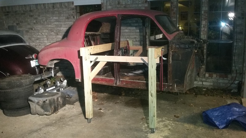
This was a fairly tricky step that required time to think through the process. I was initially unfamiliar with how the body mounted to the frame and did not have a normal shop lift like reputable restoration shops would have. My ultimate solution was to build a wooden frame through the door openings of the body and use 1000 lb rachet straps to lift the body. My guess is the empty body weights about 500+ pounds so it is probably possible to have 4 people lift it off manually.
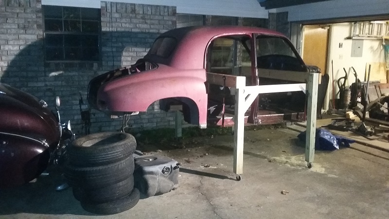
The body has a total of ten 3/8" BSW (British Standard Whitworth) bolts with 5 on each side that are fastened horizontally parallel to the ground to mount points on the frame. Two are near the rear end next to where the rear bumper mount bracket is located. Along the front and rear door sills are 3 mounts on each side. Two are located on the front of the body near the frame next to the steering box or idler mount brackets.
The challenge with lifting off the body is it's strongest on the corners, that is, you do not want to use the straps to lift at the open portion of the door sills because they will bend under the weight of the body and get damaged. I used two floor jacks to hold up each front corner of the body, removed all the bolts except the rear 2 that were loosened. Then I jacked up the body enough to slide 2x4 lumber along the back side of the door sills and screwed them in place using the original body mount bolt holes. That was used to better distribute the load on the straps. At this point, both straps were run under the body and attached to the rolling wood frame. The front strap was tightened just enough that the floor jacks were no longer needed. Then the rear 2 bolts were removed and the rear end was lifted up using the rear strap. Then the whole thing was lifted up further using both straps.
The other thing I did was remove the two rear tires to lower the rear end as much as possible to avoid having to lift the body very high off the ground to be able to clear the highest point at the rear crossmember.
The rolling wood frame is constructed with 4x4 lumber for the legs with 300lb casters on each leg. The horizontal crossmember of the frame is a single 2x6 about 2 feet wider than the body width. The 2x6's are fastened to the 4x4's using large 1/2" bolts and further reinforced with steel straps and 2x4 cross braces.
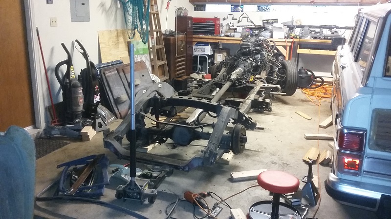
Frame and Drivetrain Inspection
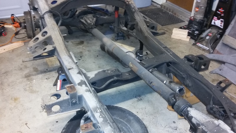
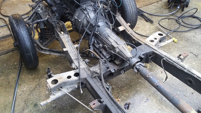
An original P4 would have a 2-piece driveshaft (aka a propeller shaft). The first stationary shaft runs from the transmission to the rear crossmember that was in front of the axle. The second shaft has an U-joint and spline from the end of the first shaft down to the axle differential. The spline allows the shaft to change length as the axle moves vertically. With the Toyota A43D transmission, the previous owner changed the original driveshaft configuration to a simple single solid shaft from the transmission to the differential axle.
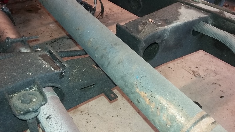
The crossmember directly in front of the axle had a notch cut out to provide clearance for the new driveshaft. This notch was unsurprisingly done with the body still on the frame because new welds were only done on the sides of the crossmember.
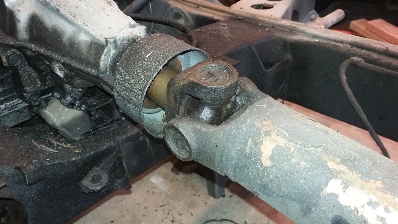
Instead of a driveshaft spline, the A43D transmission uses a slip yoke that moves in and out of the transmission body to compensate for the differential axle vertical motion.
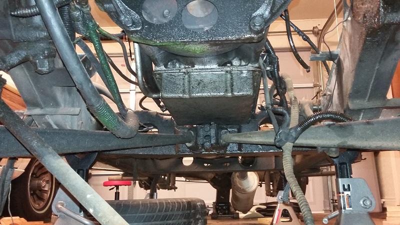
The transmission drain pan bolt is right above the rear mount for the front suspension wishbone and incredibly difficult to access if the fluids were ever to be changed. The transmission also appeared a bit off center. As it turns out the transmission mount was attached to the frame with a single 3/8" bolt. The previous owner's driving evidently caused the bolt to come loose and carve a larger hole in the crossmember so the transmission was free to rattle around! Definitely on the list to remedy.
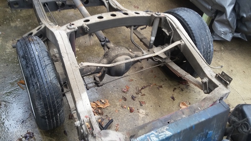
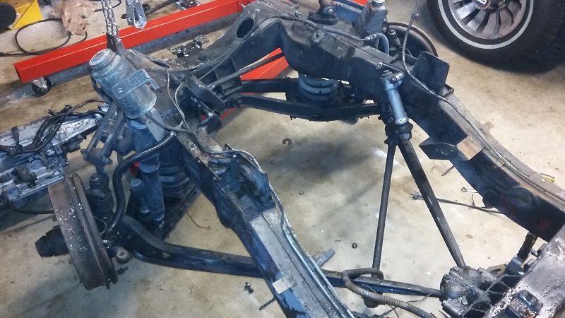
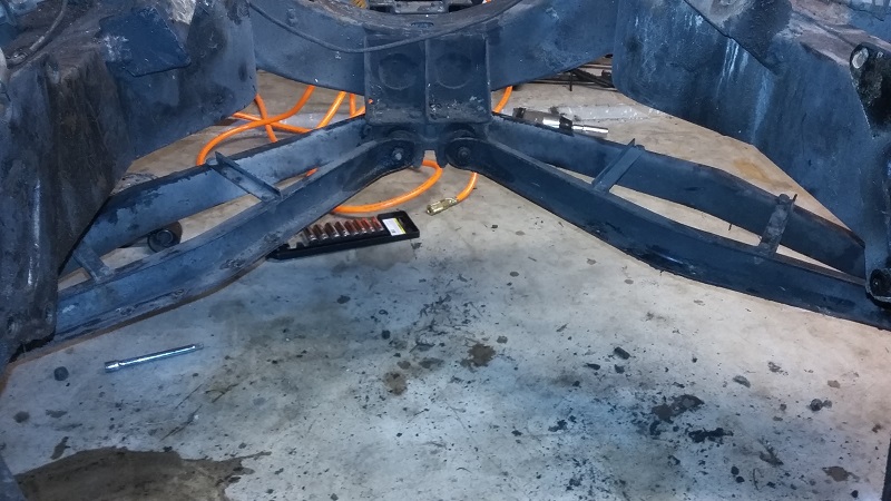
A view of the grease and dirt covered frame before power washing.
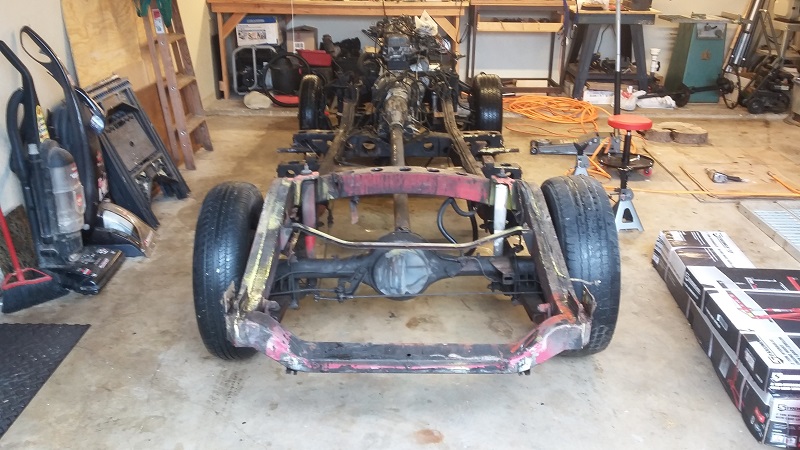
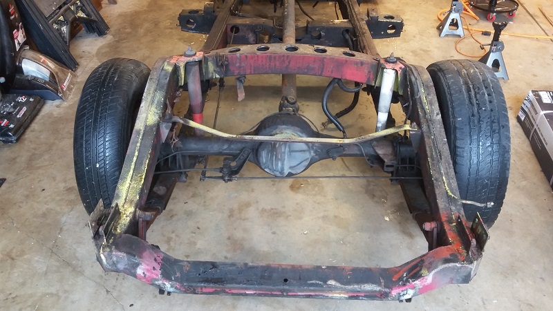
After power washing, the frame revealed many paint colors that makes it hard to imagine what was original. Red, orange, yellow, gray, black, and blue were among the many blotches of colors found on the frame. All of the grease, dirt, and coats of paint definitely did their job at keeping the frame remarkably rust free!
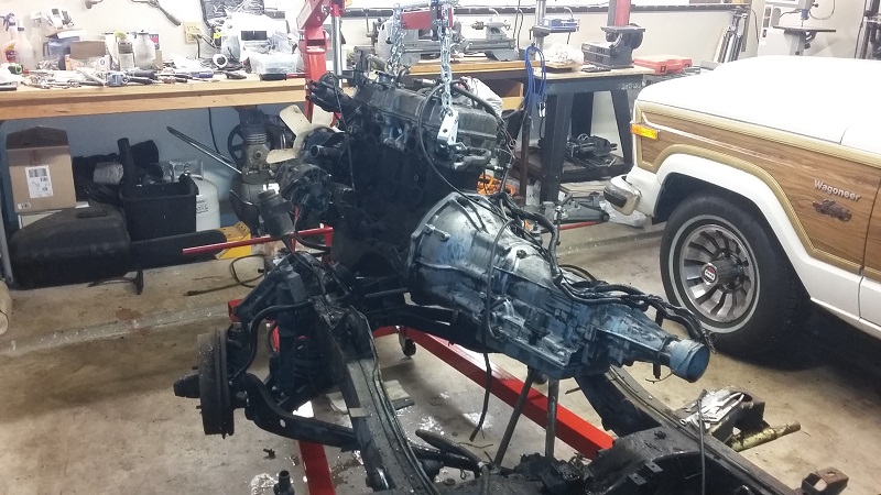
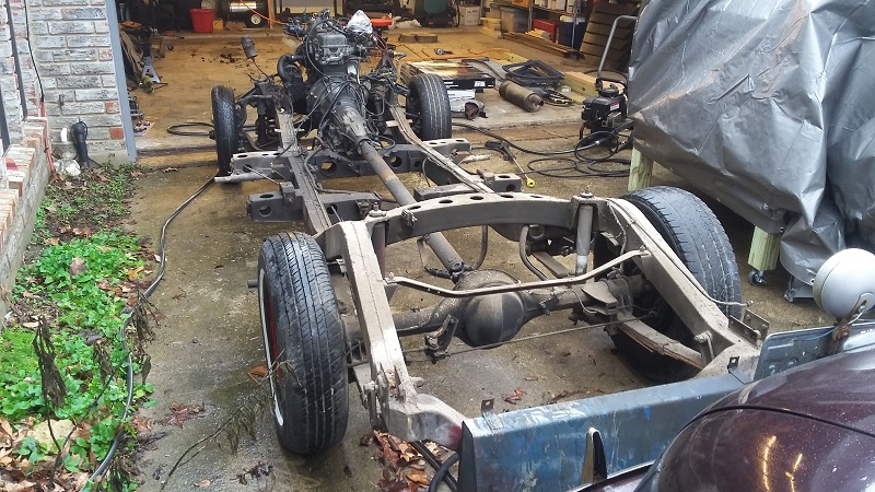
Engine and transmission hoisted off the frame to be dealt with at a later time.
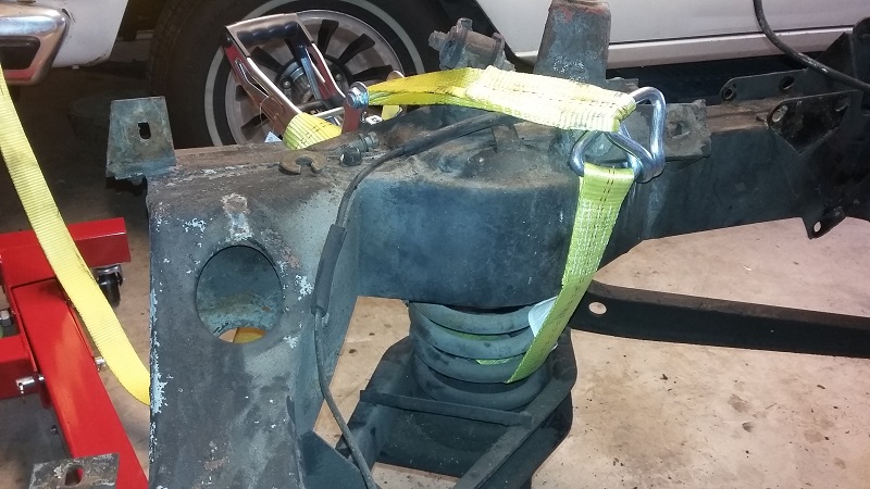
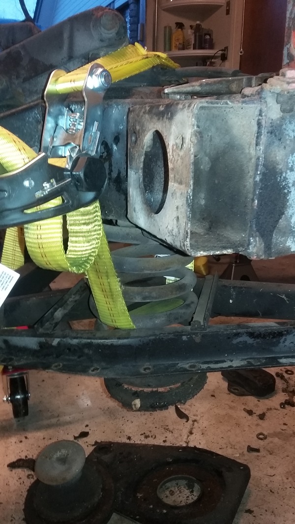
The coil springs on the Rover are partially hidden inside the frame and the bottom plate so modern spring compression tools do not work on these. Some compression tools require insertion inside the middle of the spring, but unfortunately the P4 has sizable bump stops inside the springs that prevent using those tools. In fact, the official shop manual recommends using a floor jack positioned directly under the spring and use a chain from the bottom of the jack to the top of the frame to ensure the jack doesn't simply push up the entire frame. A different approach I took as illustrated in these pictures is to use a 10,000 pound rachet strap to slowly compress the spring in order to remove the bottom plate, and then slowly and carefully decompress the spring. This method was successful and trouble free!
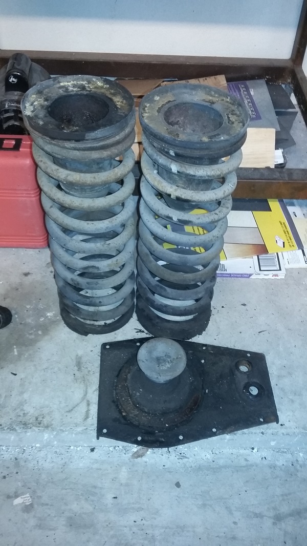
Springs removed from front independent suspension so the remaining suspension components can be removed from the frame.