Basic Relay Computer
Return to Home
Return to Projects
Interested in building relay logic circuits? Consider buying Catahoula Technologies Relay Logic Modules and read more about them in the Relay Logic Projects.
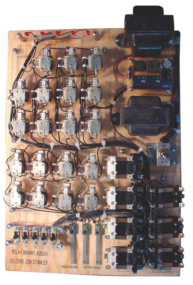
I obtained roughly 35 NOS relays for free from a friend who was cleaning out his garage. There was a forum discussion about vintage relay computers of the 30s to 50s, where various schematics of relay half-adders and full-adders were devised. I modeled my relay computer after the Homebuilt Computer in "How Things Work" by Neil Ardley. Basically the computer shown in the book has four data switches for 4-bit data and a switch to select the memory location A or B. The data is loaded into one of two memory locations of a 4508B 4-bit flip flop IC that serves as memory. The bits stored in memory can be read one at a time or summed through the 4008 4-bit binary adder. The binary output was decoded with a 4511 decoder to a 7-segment display.
Note that this basic relay computer is not a fully operational CPU, but actually a simple 4-bit relay adder with two 4-bit input storage/registers. This is as basic as a "computer" can get. Below are schematics of the half-adder and full-adder circuits that were devised by others at a forum.
The idea was to omit everything that was solid-state (except for the power supply rectifiers) in the computer design. The relay adder circuits were used to create a 4-bit relay adder using eleven (11) relays. I designed the memory using the same relays used in the adder and latched them electricially. Basically, when you energize the coil and the relay closes, the switch passes through the current to the coil and keeps it closed unless shorted. Fortunately, with three resistors, a delicate balance was achieved so the relay could self-latch on a low or high signal without any shorting out. The first basic memory design used only one resistor, which poses a problem with current draw when the bit is supposed to be zero. The adder would attempt to draw current through the memory relay if it sees a zero, and that caused the memory relay to turn on. Below are the three revised versions of the relay memory, rev. A being the first idea and rev. C being the final plan used in the computer.
I initially planned to use small low-power relays as an oscillator and wire a neon bulb across the coil. As a result, the inductive kick-backs from the oscillating coil would light up the neon bulb, and I made five to display the output data. More information on this circuit can be found at the bottom of the page here: The Noisy High Voltage Generator. However, the current draw of this caused issues with the memory and adder, resulting in incorrect calculations so the idea was abandoned and LEDs were used. I would have used regular light bulbs instead to avoid using solid-state parts, but I decided to go with the LEDs because that was what I had on hand. The important point is, the entire adder and memory functions entirely on electromechanical parts; neither the LEDs nor the rectifiers have any part in the processing. Below is a block diagram of the relay computer.
To use the computer, one would set the data switches for a certain binary number and select an address location (A or B). Address B would set a couple relays to direct the 4-bit data input to the string of latching relays for memory B. If on A, then those relays are off and by default sends the data to memory A. Once the address location and data bits are set, one would press PROGRAM, which would activate a relay that would send the 12V (high) and 0V (low) through the data switches, then through to the memory relays, setting certain bits and resetting others. The adder by default will perform addition of zero plus zero and this is reflected on the LED output unless one presses the pushbutton A or B, which would add A to zero or B to zero (this basically indicates what is stored in a memory location). If one presses BOTH buttons, then the adder will read both memory locations and yield the sum. The maximum sum is 11110 (30) with both inputs maxed at 1111 (15).
Subtraction can be performed by adding a number with another that is negative. However, since this computer is more like an ALU and cannot process instructions, the operator has to do preliminary preparations for creating the negative number using two's compliment. For example, 1100 (12) - 0101 (5) requires that you invert the smaller number (I could use a XOR function on my computer by disconnecting all carry functions on the adder for a XOR comparsion between 5 and 1111 (15)). 0101 (5) is inverted to 1010 (0 becomes 1, and 1 becomes 0). Then add one... 1010 (10) plus 1 (for the subtraction carry) is 1011 (11). Finally add the larger number 1100 (12) and 1011 (11) through the adder, which will yield 10111. For subtraction, the carry to the fifth bit (16) is ignored and we only concentrate on the four bit result, which is 0111 (7).
Another example of subtraction: 15 minus 6. Invert the binary bits for 6. 0110 (6) => 1001 (9). Add 1 to the inverted number. 1001 (9) + 1 => 1010 (10). Finally, 1111 (15) + 1010 (10) = 11001 and the 5th bit is ignored. Result is 1001 (9).
The same general design of this computer was completely reinvented using Catahoula Technologies Relay Logic Modules and documented under Basic Calculator (Binary Adder/Subtractor with Memory).
Back to Top