Single Meter Clocks
Return to Home
Return to Projects
Clock using all discrete logic
My attempts at creating an alternating display for my version 1 nixie clock led me to think of new logic designs for switching signals to the display. I took the design of my version 1 nixie clock, tossed out the 4013 flip flop and two 4017 counters, and redesigned the hours section and the reset circuits. A 4081 (quad 2-input AND gate) was used instead; a single gate serves as a Set/Reset bistable, another gate basically takes in the signal when the hours reach 13 and goes HIGH to reset the hours, and the last two gates serve as buffers (one for the 60Hz line).
The schematic is too large to be displayed here, so please click here to view the schematic.
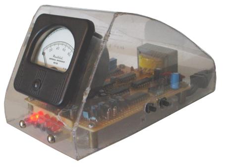
There were several modifications mainly to drive a single meter (the meter used is a Heathkit "Antenna Impediance Meter" or a 0-100uA meter). The outputs of the 4017s were converted to analog signals using a homebrew DAC with a chain of transitors and resistors. First, a 500K pot was used and wired with one transistor in series. Tune the pot to one digit on the meter, record the resistance of the pot, retune the pot to the next digit, record the resistance, and so on. A resistor ladder was created from the recorded resistances to convert the digital signals to analog signals. For the meter to display 0, the resistance is open and the meter outputs nothing. For the meter to display 1, the signal has to go through the entire resistor ladder (total of about 520K), for 2, it goes through less resistance, and so on until the least resistance causes the meter to display 9 (maximum). The clock circuits are always on so there are always four analog signals being produced. A 74HC4851, a cool 8-channel analog switch mainly for audio, is used to switch one of the four analog signals to the meter. A separate 4017 and a free running 555 oscillator set to be variable from around 1/4Hz to 1Hz is used to switch the channel inputs on the 74HC4851 to allow the display speed to be adjustable.
Another modification I made to the circuit was to eliminate the FAST and SLOW set switches. Of course, this method would be terribly difficult to set the time while only being able to view one digit at a time. Instead, a pushbutton is used to set the hour and another pushbutton to set the minutes.
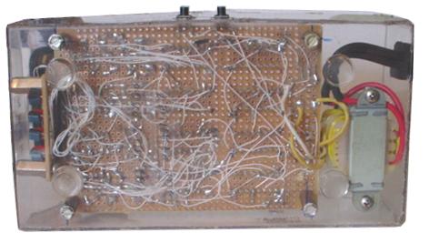
The power supply is relatively safe consisting of only a 25VCT transformer that was found in my junk pile and produces about 13VDC after rectification. The 13V is then reduced and regulated to 5V with the 7805. The 60Hz signal is obtained from one side of the transformer before the rectifiers.
Four LED displays were wired off the 4017 chip that switches the channel inputs on the 74HC4851 to light in sequence. Notice that channel 1 (Y0) on the 74HC4851 and output 1 (Q0) on the 4017 are left disconnected. This is so on the first output of the 4017, no signal is passed into the channel selector inputs, so they are pulled down to LOW via the 6K resistors and the 74HC4851 is automatically on channel 1 (Y0). As a result, the meter and the LED indicators are off. I call this the blank state so the viewer would know that the meter is just about to start displaying the time. Finally, when output 1 of the 4017 goes HIGH, the channel increments to the second channel (Y1) so the meter displays the 10 hour (either 0 or 1), and the first LED is lit. The next output of the 4017 selects channel 3 (Y2), meter displays the 1 hour (0-9), and the second LED lights. The fourth 4017 output selects channel 5 (Y4) because the binary input is 100 (4) and the meter displays the minutes. Finally, the fifth output of the 4017 will activate both input B and C for a binary value of 110 (6) to select channel 7 (Y6) to display the minutes. This is an easy way to avoid using unnecessary logic gates to decode decimal into pure binary or vice versa. The display cycle starts all over again when the 4017 goes to the 6th output (Q5) and resets itself to bring the meter back into the "blank state."
Ever since the circuit was fired up, it runs very well 24/7 without a speck of a problem, in fact, much more reliable than the version 1 nixie clock.
An animation of the clock in action displaying 0, 2, 1, 6 or 2:16 for the time.
Clock using PIC microcontroller
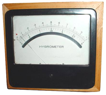
The second single meter clock design is much simpler and runs off a PIC 16F84A microcontroller. The software is the same as the one used in my Single Digit Nixie Clock. The decimal output from the PIC makes it possible to use 10 diodes and resistors for an inexpensive DAC. I used a large hygrometer with a 500uA scale. Below is the schematic of the second single meter clock:
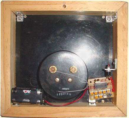
I used 9 small 50K pots and two resistors so the pointer can be adjusted for each digit. The PIC cycles through each digit of the time relatively quickly that the meter has insufficient time to stablize its pointer on a digit before the PIC moves on to the next digit. Perhaps the inertia from the pointer is not a problem on a smaller meter. However, I adjusted the pots for each digit to compensate for the inertia while the clock is in operation. When you set the time, the meter will point a little before the digit, but in operation the pointer will hit the digit due to the momentium.
Although this clock has no digit indicators (HHMM) like the first meter clock, I added a micro LED just above the zero on the scale as a zero indicator. If the meter points at zero and the LED is off, then the meter is assumed to be blank. If the time was 10:00 then the meter will point to 1 then fall to zero and the LED will flash three times. The clock runs off a 6-volt battery and is mounted on a wall.