Single Digit Nixie Clock
Return to Home
Return to Projects
Single 10-cathode Nixie Clock
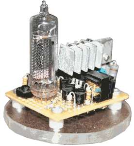
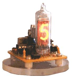
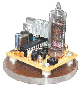
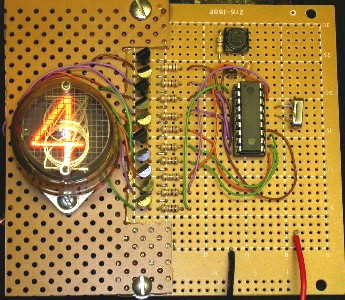
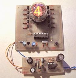
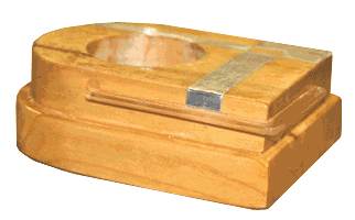
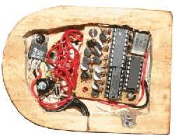
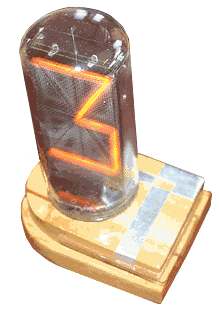
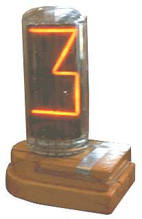
This is a single-digit nixie clock running a modified program of the single Numitron and VFD clocks. The PIC 16F84A outputs 10 signals for each cathode of a single nixie, and flashes the digits instead of using the four indicators. The clock was a great challenge because I chose to use the same size board used on the other single digit clocks (roughly 1.25 by 1.5 inches). The main challenge was to obtain high voltage without using 120V mains, which is done with a miniature high voltage generator salvaged from a disposable camera. The PIC, crystal, 10 transistors, resistors, and the high voltage generator were all crammed on the small space of the board using virtually every space available.
The high voltage generator consists of a basic self-excited oscillator with a small high voltage capacitor on the output and a 1Meg resistor to level out the voltage to roughly +340VDC. The high voltage generator draws 200mA at 1.5V, so a 18 ohm resistor from the 5V regulator is used to drop the voltage. A small heatsink (which gets relatively hot easily) was mounted on the 5V regulator to sink the heat because of the heavy 200mA draw from the high voltage generator.
The .ASM file is the PIC assembly program for the clock. The .HEX file is the assembled program used to program the PIC, but choose the correct HEX file depending on whether you want to use a 3.57MHz or 4MHz crystal. Bad timekeeping will result from incorrect matching of the HEX file and crystal speed.
24 Hour Nixie Clock
24nixclk.asm (.ASM file)
24nixclk3.hex (.HEX file) 3.57MHz
24nixclk4.hex (.HEX file) 4MHz
12 Hour Nixie Clock
12nixclk.asm (.ASM file)
12nixclk3.hex (.HEX file) 3.57MHz
12nixclk4.hex (.HEX file) 4MHz
NOTE: There is a chime logic pulse output on pin 2 (RA3). The logic output will give a number of pulses in accord to the hour when the minutes turn to zeros. For instance, there are 8 logic pulses from pin 2 when the time turns to 8:00. The output is not an audio frequency, it is a simple logic pulse, so one would need an tone or chime generator for the audio.
NOTE 2: Holding down the time set switch while the clock is first powered up will set it in a test mode that cycles through all the digits. It is useful to kill off some "cathode poisoning" on nixies that have not been used in a while.
Single B7971 Nixie Clock
This clock uses the large alphanumeric B7971 nixie tube rather than a standard 10-cathode nixie tube. The PIC program was modified to drive all 14 segments of the B7971 to give each digit an unique appearance as opposed to the plain 7-segment arrangement. One challenge was to directly drive (not multiplex) 14 segments of the B7971 from a PIC 16F84A that only has 13 port pins. Moreover, one pin is reserved to set the time and another to provide the chime logic output. As a result, only 11 pins were available to control 14 segments.
The same hardware tricks used with the nixie propeller clock were used on this design; a pair of XOR gates and an AND gate to "magically" create another control signal for a segment. Please refer to the nixie propeller clock notes for more information on how this logic circuit works. Additionally, the XOR/AND logic cannot be used with just any two outputs of the PIC like the nixie propeller clock because many segments are used again for several digits, i.e. segment A at the top is used for digits 0, 2, 3, and so on. The image below shows the styles I chose for each digit:
Notice that the digit 1 only uses the center segments so these are tied together, and thereby only 13 control signals are necessary rather than 14. The logic is used to control another segment that is used rarely by "activating" a pair of other segments that are not both used by all the digits. For instance, the left upper diagonal and left lower diagonal are never both on for any digit, so by programming the PIC to give out a signal for both of these segments, the XOR's shut these segments off and the AND gate will produce an additional control signal for another segment. This is how I avoid multiplexing the display and have all segments turn on continuously.
Please note that in the schematic, the numbers shown in the nixie symbol are the actual pins of the nixie and not the segments. For the programs below, the .ASM file is the PIC assembly program for the clock and the .HEX file is the assembled program used to program the PIC. The HEX files are for a PIC running on a 4MHz crystal only.
24 Hour Nixie Clock (.ASM file)
24 Hour Nixie Clock (.HEX file)
12 Hour Nixie Clock (.ASM file)
12 Hour Nixie Clock (.HEX file)
A camera flash power supply could be used for the clock, but a single power source (i.e. 5V) cannot be used with the camera flash power supply because it provides negative high voltage with respect to ground. Reversing the diode in the camera power supply to produce a positive high voltage source with respect to ground produces very little power and only works for smaller nixies such as those used in the single digit nixie clock above or the nixie propeller clock. A B7971 hungers for current, so this little trick with the camera power supply did not work effectively for me. Also the case I built had extremely limited space so a larger high voltage generator (DC-DC converter) will not fit. My solution was to use a simple 170VDC mains supply that provides sufficient power for the B7971 and the PIC.
The case was designed in an art-deco flair using interesting geometric appearances. One side is curved like a semicircle while the other side has corners like a square. Moreover, there is a small L-shaped strip of plexglass in the wood that was going to be lit with some LEDs but that didn't happen due to size constraints. The case was intended to appear small and slick, which resulted in problems with where to place the electronics. I had hoped to use a chime with this clock, but there was simply no room at all. However, the PIC outputs chimes on RA3 if you want to use it.
Back to Top