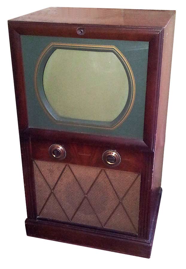
Sentinel 416 Restoration Notes
Return to Home
Return to Resources
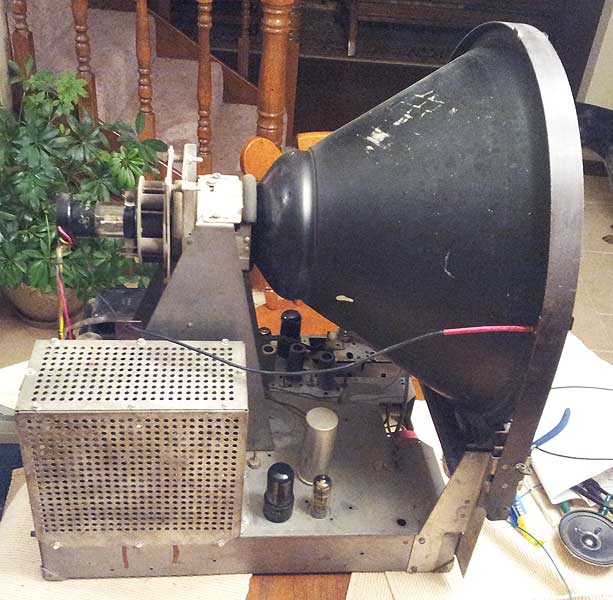
The TV originally had many problems with the power supplies including a history of fire in the high voltage section and bad B+ rails. All the electrolytic filter capacitors had to be replaced. One notable issue in particular was the main B+ filter capacitors were 475V rated and most new electrolytic capacitors tend to be rated 450V at the most. I had located 500V replacements from a radio swap meet, but after installing them, the 5U4 rectifier tube instantly put on a fireworks show when turning on the TV. It took me several weeks to realize that the filter capacitors I had put in were dead shorts even though they were correctly rated for the voltage and installed properly. Just because they were "new" from a radio swap meet doesn't mean they were good! I ended up having someone make me a custom filter capacitor replacement that worked.
Also, obviously all the paper capacitors had to be replaced. This process was fairly straight forward for the most part. The chassis undereath the high voltage cage was all charred black as a result of an exploded paper capacitor and a broken power resistor. At the time, this was a challenge for me to repair because in order to determine the original component values to replace them, I had to learn how to trace the connections in the chassis and correlate it to the schematic. Also several wires in the charred high voltage area had their insulation burned off and needed to be replaced. Many power resistors were replaced with new higher wattage ones and several other out of tolerance resistors were replaced.
The next major problem was the vertical positioning potentiometer was bad. It is a 20 ohm wire-wound pot with a center tap supplying power to the vertical deflection yoke. The slider portion of the pot would adjust the DC voltage on the other side of the deflection yoke that the vertical ramp oscillator drives. Unfortunatley, the pot went open from the main B+ input rail resulting in all the other rails not coming up. Several other TVs of similar design from this era tend to be afflicted by similar problems with failed potentiometers (not necessarily a vertical positioning pot) when used in the power supply section. Replacement potentiometers with a center tap are as rare as hens teeth to find nowadays, so I replaced it with a standard 40 ohm potentiometer and used two 20 ohm resistors connected in series and placed in parallel across the 40 ohm potentiometer. This produces an equivalent 20 ohm resistance as the original potentiometer did, but the center tap now comes from the series connection between the two 20 ohm resistors.
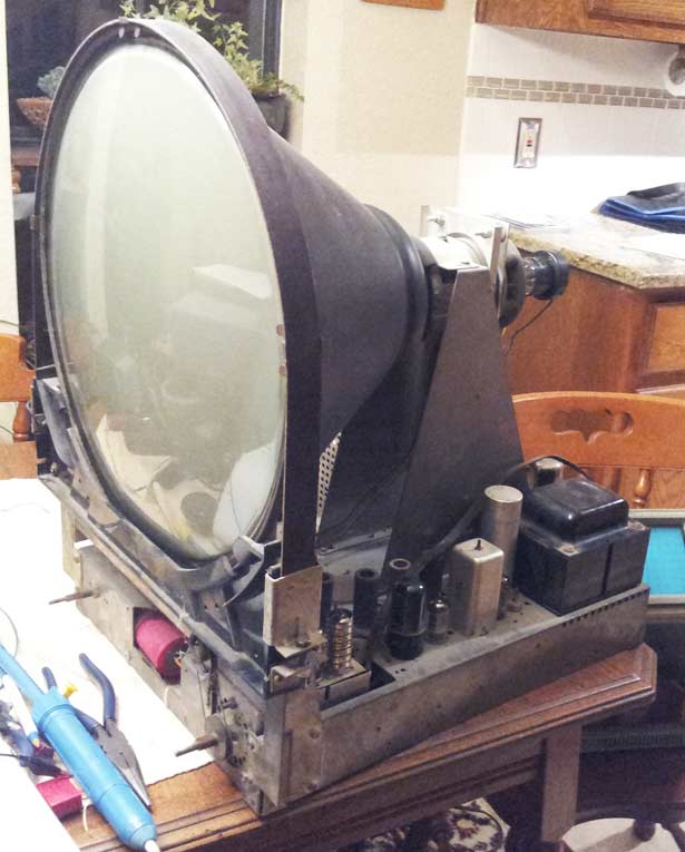
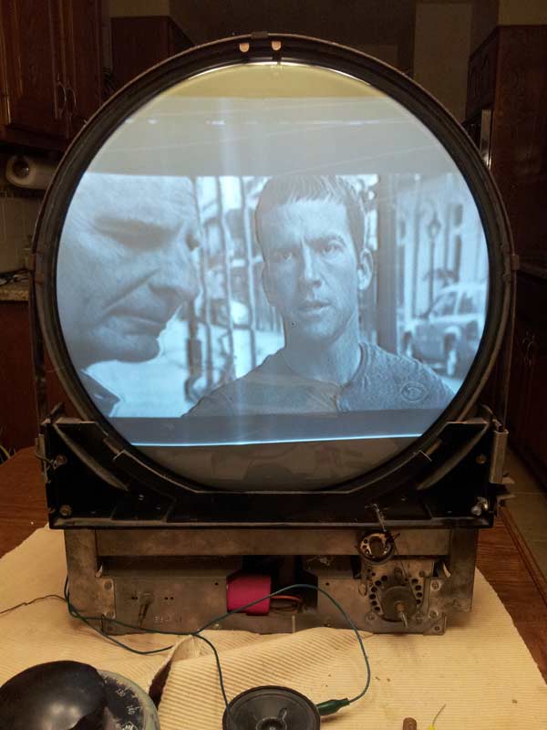
Repairing the vertical position control pot restored power to most of the B+ rails and the high voltage was functional once again. A quick way to verify the high voltage is functional is either by bringing a neon bulb near the transformer and see it glow without making contact or using a screwdriver to draw an arc off the plate of the 1B3 HV rectifier tube. However, the TV still refused to produce a picture. After fiddling with the controls and slightly tweaking the ion trap, I noticed a very dim raster visible in a dark room as shown in the following picture.
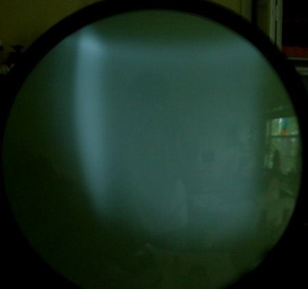
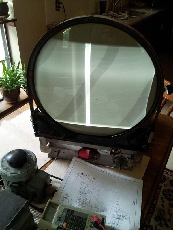
So the original issue I left off was the raster was very dim despite restoring the B+ rails and having functional high voltage. Since a decade had passed since I last looked at the chassis, I decided to reinspect my work and check voltages. All the B+ rails were functional but a little higher than the schematic called for. In my inspection, I uncovered an old mistake in forgetting to connect a wire to the vertical centering pot so the vertical oscillator wasn't properly receiving power. After a quick correction, the B+ rails all came back within expected range with the slight added load of the vertical oscillator. After most of the voltages seemed reasonable, there was no explanation for the dim raster. I started to wonder if the ion trap was misadjusted since I don't recall ever touching it in all the time I've had the TV. I just assumed it was in the correct position or was close. After sliding the ion trap magnet back and forth and rotating it 90 degrees clockwise or counter-clockwise and seeing no improvement, I decided to just rotate it 180 degrees and suddenly a bright raster finally appeared!
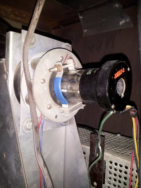
CRTs made prior to the late 1950s just had a phosphor coating behind the glass screen so light generated by the phosphor excited by the electron beam would illuminate inside the CRT as well as on the screen so picture brightness was limited and inefficient since light going into the CRT was not visible and wasted. Newer CRTs made after the late 1950s have an aluminium coating behind the phosphor intended to reflect all light from the phosphor outward from the screen to significantly improve brightness. The ancillary benefit of the aluminized coating was that it protects the phosphor coating from ions so straight-gun CRT assemblies could be used again without an ion-trap. However, some TVs in the late 1950s may have an aluminized CRT with an ion-trap because the CRT still has an angled electron gun.
Now that I was able to get a picture on the screen of the Sentinel 416 for the first time in probably a few decades, there was clearly some more work left to do. The vertical and horizontal frequencies were still far off and the horizontal had extreme non-linearity causing a vertical bar in the middle of the screen. I used a TV test pattern generator to feed a test image and proceeded to adjust the sweep oscillator frequencies. The horizontal drive strength was adjusted to eliminate the vertical bar in the raster. The picture came through alright, but the contrast control was not working very well and the audio was not coming through well. After studying the schematic, I noticed that Sentinel designers decided to use the current flow through the audio amplifier circuit to generate a 125V rail to be used as a bias voltage for the IF and video amplifiers. It appears that some video AM noise from the IF and video amplifiers can bleed onto the 125V rail resulting in a soft sync buzz noise coming through the audio that seemed difficult to completely eliminate given the way the circuit was designed. The other downfall of this strange 125V rail design is that if the 6K6 audio output tube got weaker then the rail voltage would decline resulting in the contrast control losing effectiveness.
I pulled all the tubes and checked them on a tube tester. Nearly all of them were weak or had intermittent shorts so they were replaced. I followed the IF and audio alignment instructions for the Sentinel 416 to peak the coils. Most of the coils were already spot-on. The 6K6 audio output tube was replaced and the 125V rail came back up to within range. For comparison, the Admiral 19F1 TV circuit design supplied all rails directly from the power supply without generating them in weird ways like Sentinel did with the 125V rail so it was no wonder the Admiral was way easier to repair.
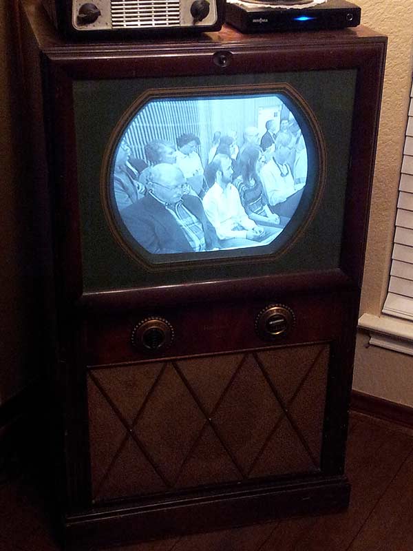
With a DTV tuner box hooked up to the TV, I was able to bring in stations nicely as shown in the following pictures. One annoying design aspect of this TV is that all the vertical and horiziontal controls are in the back so if the picture started flipping, it was a royal pain to find the control in the back to correct this.
So there you have it, the TV has been resurrected after well over a decade if not decades and works well. The cabinet was in good original condition and did not require any refinishing. This concludes the culumination of 13 years of my repairs.
Back to Top