LC Oscillators in Radios
Table of Contents
1. Introduction
2. The LC Oscillator
3. Armstrong Oscillator
4. Hartley Oscillator
5. Colpitts Oscillator
6. Crystal Oscillator
7. Electron-coupled Oscillator (ECO)
8. Conclusion
Introduction
The LC Oscillator
Technically this basic LC circuit generates a sine wave that loses voltage in every cycle. To overcome this, additional voltage is applied to keep the oscillator from losing voltage. However, to keep this oscillator going well, a switching method is used. A vacuum tube (or a solid-state equivalent such as a FET) is used to keep this LC circuit oscillating. The advantage of using a vacuum tube is that they can oscillate at specified frequencies such as a thousand cycles per second.
There are several different types of LC oscillators. A little off subject; one well known and entertaining oscillator is known as the tesla coil, which uses an unique LC circuit using the spark gap to oscillate.
Armstrong Oscillator
When current flows in the plate, a electromagnetic field gives feedback to the tank coil, which keeps the oscillations going. The grid resistor drops the voltage, thus the grid is very negative with respect to the cathode. The grid capacitor keeps enough charge to keep the grid negative for at least one cycle of oscillation, it helps keep the grid negative when either side of the LC circuit is postive. When the LC circuit's postive charge is at it's maximum, the charge will balance with the grid capacitor, causing plate current to flow because there is no negative on the grid. This is the point when the tickler coil provides feedback to the LC circuit. The grid controls the plate current in all vacuum tubes, thus if the grid oscillates this number of times, the plate will oscillate the the same number of times, the tickler coil will give feedbacks at the same number of times. This is because of the tank circuit, which specifies the frequency. The frequency can be adjusted when the coil and/or capacitor are adjusted. The bigger the coil and capacitor are, the lower the frequency. The smaller the coil and capacitor are, the higher the frequency. However, in an antique radio, it is handier to adjust the capacitor than the coil to specify a frequency so a variable capacitor is used. This is a very typical feedback oscillator, however the greatest disadvantage of this oscillator are unstable frequencies.
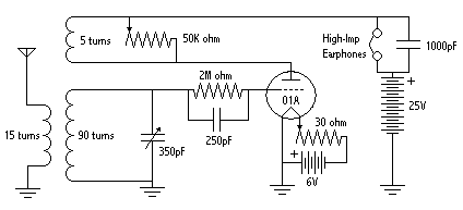
Some of you may be familar with this circuit. This circuit is also known as the regenerative receiver Edwin H. Armstrong developed. Below is a basic regenerative radio circuit you can construct that is similar to the Armstrong oscillator.
Hartley Oscillator
The cathode is tapped to the coil so when current flows through the coil, there is a voltage kick in the grid coil. The amount of feedback is controlled by changing the cathode tap. Most of the LC circuit works in a manner like the Armstrong oscillator. The Hartley oscillator is an improvement on the Armstrong oscillator, however it has some frequency instabilities.
Colpitts Oscillator
The tap between the two capacitors is grounded and the feedback is obtained from the coupling capacitor, C1. The amount of feedback depends on the ratio of C2 to C3. The capacitor part of the LC circuit consists of both C2 and C3, which determines the oscillating frequency. This oscillator has more frequency stablities than the Hartley oscillator.
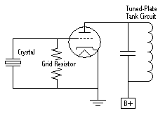
Crystal Oscillator
Notice there is a LC circuit on the plate circuit now. As said earlier, the crystal vibrates at its own frequency, so the LC circuit is on the plate to adjust the amplitude of oscillations. However, more components are suggested in this circuit to maintain the voltages and RF in the circuit. The disadvantage of this oscillator is its limited power output.
Caring and feeding of a crystal is important. Crystals will overheat or crack when fed with too much voltage. The current flowing through a crystal generally should not be more than 100mA (.1A).
Electron-Coupled Oscillator (ECO)
The circuit functions very much like a Hartley oscillator except feedback is obtained from the screen grid instead of plate. A dropping resistor is used in series with the screen grid and B+ because the screen grid uses less power compared to the plate.
Conclusion
Electronic oscillators are commonly found in everyday circuits, ranging from antique radios to the transmitter in your TV remote. The basic job of an electronic oscillator is to generate an oscillating output often at a constant frequency. Various outputs can be sine, square, sawtooth, triangle, or complex waveforms. This article explains basic sinusoidal LC oscillators.
This oscillator consists of a capacitor and a coil connected in parallel. To understand how the LC oscillator basically works, let's start off with the basics. Suppose a capacitor is charged by a battery. Once the capacitor is charged, one plate of the capacitor has more electrons than the other plate, thus it is charged. Now, when it is discharged through a wire, the electrons return to the postive plate, thus making the capacitor's plates neutral, or discharged. However, this action works differently when you discharge a capacitor through a coil. When current is applied through a coil, a magnetic field is generated around the coil. This magnetic field generates a voltage across the coil that opposes the direction of electron flow. Because of this, the capacitor does not discharge right away. The smaller the coil, the faster the capacitor discharges. Now the interesting part happens. Once the capacitor is fully discharged through the coil, the magnetic field starts to collapse around the coil. The voltage induced from the collapsing magnetic field recharges the capacitor oppositely. Then the capacitor begins to discharge through the coil again, generating a magnetic field. This process continues until the capacitor is completely discharged due to resistance.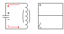
This oscillator is very much like a RF amplifier, but a new coil, called the tickler coil, is connected between the plate and the B+, or high voltage supply. This coil is generally wound next to the main LC coil, or tank coil.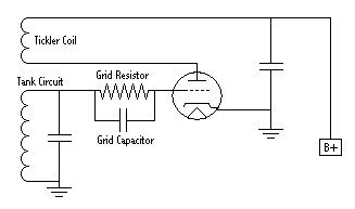
This oscillator is very similar to the Armstrong oscillator and is commonly used. The difference between the Armstrong oscillator and the Hartley oscillator is that the tickler coil is part of the LC circuit. This oscillator is easier to tune compared to the Armstrong oscillator.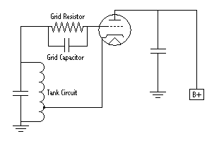
The Colpitts oscillator is very similar to the Hartley oscillator, but instead of a tapped grid coil, it has tapped capacitance.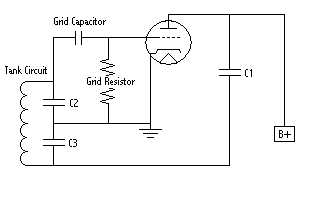
This is a type of oscillator that is controlled by a crystal. The big advantage of a crystal oscillator is high frequency stablility. Common crystals used are tourmaline, Rochelle salts, and quartz. The crystal makes a voltage difference when voltage is applied to the two plates on the crystal. When AC is applied, the crystal compresses and stretches, in other words it vibrates. The natural frequency of a crystal's vibrations is found to be more constant than the oscillations in a LC circuit. The thinner the crystal is, the faster it vibrates. The LC circuit is the electricial equilavent of a crystal.
This is a unique oscillator that generally uses a pentode, sometimes a tetrode. This oscillator has advantages over the previous oscillators, such as good frequency stabilities. Below is a ECO equilavent of the Hartley oscillator.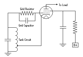
Now you have learned about some of the oscillators used, you can build your own for several purposes such as a radio, a tube tesla coil, a low-power transmitter, or more. There are many solid-state equivalents to the oscillators explained here in which the tube is subsituted with a transistor or a FET. Nevertheless, the circuitury is still used in the same manner as their solid-state equivalents.
Back to Top