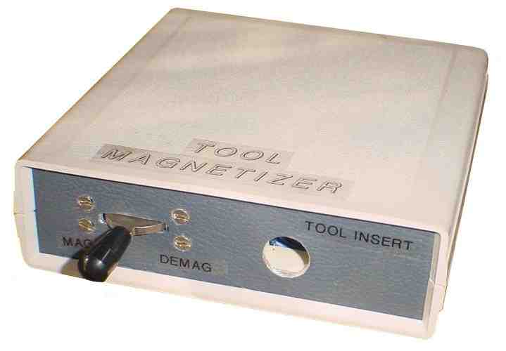
Tool Magnetizer and Demagnetizer
Return to Home
Return to Projects
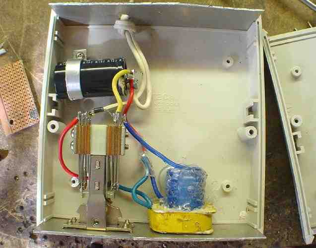
I used an AA battery as the coil form for the magnetizing coil. Eight turns of 16-gauge wire was wound on the battery then hot glue was applied to the outside to hold the coil in place when the battery was pulled out. The 220uF 200V electrolytic capacitor stores about 3 joules of energy when charged up to 170VDC. The energy is enough to magnetize a screwdriver when discharged through the 8-turn coil. The demagnetizing coil is a 120V primary winding from a wallwart transformer. The best transformer has an E-I core with the I-core removed. A screwdriver will demagnetize when in place of the I-core as the transformer is applied 120VAC. Most transformers use E-I layers that are alternated so there is no solid I-core to easily remove. I simply cut my transformer in half, which is not an easy task, to remove the 120V winding and the coil works just fine with 120VAC for demagnetizing the screwdriver.
The circuit runs off unisolated 120V mains so I strongly recommend putting the components in a plastic case for isolation and safety. The 220uF capacitor could be dangerous if charged up and mishandled. A 1Meg resistor is placed in parallel to the capacitor to bleed off the charge when the capacitor is not in use.
On one final note, the switch I used came from my stash of switches so I do not know where one can find a similar switch. It has two SPDT (single-pole double-throw) switches on both sides of the toggle. The toggle is momentary and by default stays in the center. When pushed left, the right SPDT switch changes state while the left remains unchanged. When the toggle is pushed right, the left SPDT switch changes state while the right is unaffected. If using ordinary switches for the schematic above then I would use a momentary pushbutton for the demagnetize and a double throw toggle switch for the magnetize. Note carefully that the diode rectifies 120VAC into half-wave 170VDC to charge up the capacitor. When the switch is thrown then the capacitor is disconnected from the diode and discharged into the coil. The diode should NOT remain connected to the capacitor while it dumps its energy into the coil or the diode would burn out due to 120V surging through the diode and a coil of nearly zero ohms resistance.
When using the device, I simply place a screwdriver in the coil, push the switch to magnetize, and voila! The screwdriver is magnetized almost instantly after the switch is thrown. There probably will be a "snap" sound due to the spark from the capacitor discharging through the switch to the coil. If the screwdriver is long then the tip is magnetized first then the screwdriver is moved inward and magnetized again to build up the magnetization. To demagnetize, the switch is pushed to demagnetize and the screwdriver will give a funny jerk and vibrate slightly, which is normal due to the alternating magnetic field. The screwdriver has to be forced in and out of the coil for a second or two for a thorough demagnetization.
Back to Top