Electromechanical Nixie Clock
Return to Home
Return to Projects
Nowadays I have observed that telephone stepper relays are very difficult to locate so using them in a clock is not feasible. Moreover, modern-day stepper relays are uncommon and most tend to be special-purpose steppers that do not provide the same switching options as a telephone stepper relay. I figured if I had to build a stepper relay myself, I can try to design them to best suit their purpose in a clock design. For instance, it is difficult to design the 10 minutes display to use a 10 step relay with the additional complexity of resetting the stepper relay. A 10 step relay is best suited for the 1 minute display, 6 step for the 10 minutes, 12 step for the 1 hours, and potentially another 12 step or some clever switch structure on the 1 hour switch for the 10 hour display. The possibilities are endless in how a stepper relay can be built.
One way to advance the switches is with a continously rotating motor and gears, but the downside is the hours display would most likely have a very slow transition that can result in displaying two numbers on a nixie at once and glitches. Another idea is to use a rachet mechanism similar to the telephone stepper relay, but I have never seen one firsthand to understand the design. Some videos suggest the telephone stepper relay has a reset mechanism that allows the slider to retract back to the first position. A such rachet mechanism is rather difficult for a hobbyist like me to remake.
When I acquired two pinball machines to fix up and ultimately to play on, I observed during the repairs how Gottlieb designed their decade stepper relays, called the AS relay, to control some of the lights in the Gottlieb Gridiron pinball machine. Below is a picture of the AS stepper in all its glory.
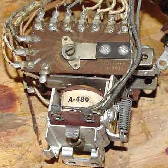
The impressive aspect of this 10 step relay was its small size. If the relay was used for the 1 minute display then it would not need a reset mechanism because the next step would instantly switch to the first position. The contacts were etched on a PCB, which makes it feasible and easy to make. There are extra contact switches on the other side that would indicate when the stepper relay was in the first position, and the pinball machine would use these switches as a signal to stop systematically advancing the stepper relay so it was reset for the next game. I used the idea of using the PCB for making the switch contacts because the PCB is easy to etch using various methods. I used a Dremel to etch my PCB. The rachet wheel used on the Gottlieb AS stepper relay is a small nylon cylinder with tiny teeth. I do not have access to fancy tools and equipment for fabricating tiny parts like the nylon wheel, so I used sheet aluminum and cut them out to create larger rachet wheels. I also bought some large 12VDC solenoids from a local electronics store to use in my homemade stepper relays.
The PCB and rachet wheels were first designed in Microsoft Powerpoint using a pie chart with the correct divisions per slice. The charts were printed out and marked on the PCB for etching and to create the correct teeth sizes on the rachet wheels. For your convenience, I went through the effort to convert the charts into nice usable images for the PCB and rachet wheels, as shown below.
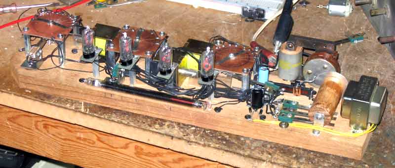
The elliptical wheels are attached to the same shaft that goes through the rachet wheel and PCB. These wheels press against a contact switch labeled SENSE in the schematic. They're used for determining when to advance the next stepper relay. The stepper relay design that I built is outlined in the following image.
The mechanical complexities of aligning the rachet wheel, the metal contact arm, and the elliptical wheels were worth the effort because the electrical circuitry is fairly straight-forward. The nixie cathodes connect to each "pie" contact on the PCB and the larger pie on the other half of the PCB is grounded. Pulsing the solenoid will advance the stepper relay to increment the nixie digit. The stepper relay is so simple considering that it performs the same function as the 4017 decade counter and high voltage transistors in a newer solid-state clock. The schematic is shown below:
The switches labeled 1, 2, and 3 are used in the sequencing unit to roll-over the digits correctly. If these switches were not present, then the digits could roll-over more rapidly and potentially glitch. The approach is that once the sense switches have asserted that the minutes is 59, the hours can safely advance first. If the minutes solenoids advanced at the same time as the hours solenoid then the sense switches could break contact and result in the hours solenoid not receiving a clean pulse to advance correctly. This "race" condition is mitigated by systematically changing the hours, the 10 minutes, then the 1 minutes in sequence.
I used a Telechron clock motor with the seconds hand attached to the motor to produce a 1RPM rotation. The rotation drives a cylinder with screws in it to produce the correct timing indicated in the schematic diagram above. One issue with this approach is that the cylinder rotates slowly (1RPM) so the duration at which each solenoid is activated is about 5 to 7 seconds each. The turn-on and turn-off transition is particularly important because if the switches labeled 1, 2, or 3 do not make or break contact quickly then the stepper relays could step multiple times. The cause is because when the switch begins to make some contact to advance the solenoid, and then the solenoid makes inductive kickback that creates an arc in the switch contact. The contact may be weak to begin with so the arc causes oscillation that causes the stepper relay to advance far more steps than one. I tested this by holding down the switch contact gently until the stepper relay started oscillating all by itself. It's quite an interesting phenomenon to see. By adjusting the location of the contact switches, their initial spacing when open and close, I was able to avoid the oscillation issue and use the 1RPM motor.
Note that I did not include switches for time setting in the circuit because I use a rather inconvenient method of setting the time. When the sequencing unit is not pulsing the contacts, I manually advance the 1 minutes to 9, the 10 minutes to 5, then set the hours to the desired time, then back up and set the 10 minutes, then finally the 1 minutes. Basically I'm setting the time in the same fashion as the sequencing unit, but this time with multiple steps if necessary as my intention for setting the time. For convenience, one may add switches between the +15V supply and each of the three solenoid coils to manually step the hours, the 10 minutes, and/or the 1 minutes.
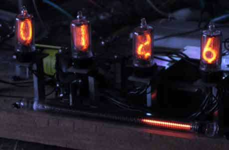
To add a nice touch to the whole thing, I added a IN13 neon tube as an analog indicator of the seconds. The seconds wheel slowly changes the resistance of a linear potentiometer to change the length of the neon bar in the IN13. In the video, you may observe a logarithmic behavior on the bar and I believe that is because i happened to pull a logarithmic potentiometer off one of the junk boards. A linear potentiometer would make more sense, though.
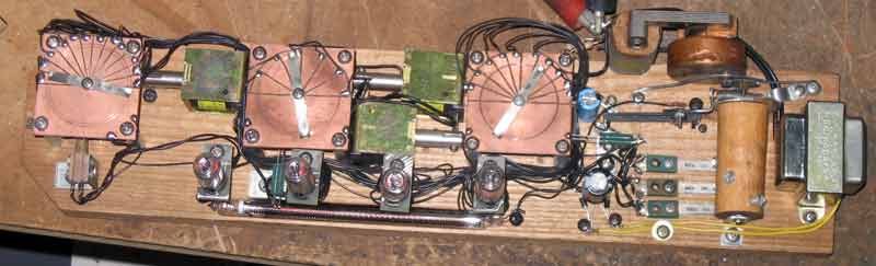
The behavior of this clock is unique because of the sequencing unit. When the time is 12:59 for instance, the 50 minute and 9 minute SENSE switches are closed so power is routed to switch 1. The cylinder closes switch 1 first so the hours rolls over to 1, but in the meantime the display now reads 1:59. Another 5 to 8 seconds later, switch 1 breaks contact and switch 2 closes to advance the 10 minute stepper to 0. Now the time reads 1:09. Finally, another 5 to 8 seconds later, switch 2 breaks contact and switch 3 closes to advance the 1 minute stepper to 0. The clock finishes rolling over the time from 12:59 to 1:00 in roughly 20 seconds. I would have preferred the roll-over to occur faster, but I found this slow reset to be neat so I left it alone. The 10 hour display runs off a double-pole contact switch that is activated by a correctly shaped elliptical wheel that maintains the contact for three of the 12 hours. The sense switches are placed under the stepper relay PCB.
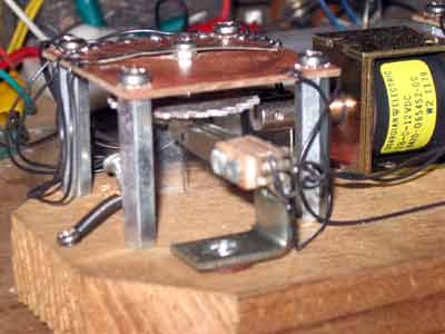
A closeup of the 12-hour stepper relay.
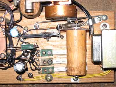
The sequencing unit. The Telechron motor is at the top and drives the cylinder that sequentially pulses the three switches. The linear potentiometer for the seconds is the black line just below the motor in the picture. A spring pulls it to the low resistance position, and the wheel presses against a metal arm to change the resistance as the motor runs.
Back to Top