World's Second Nixie Propeller Clock
Return to Home
Return to Projects
Now, about 2 years after I built my nixie propeller clock, information on the Nebulus is back! See details on the world's first nixie propeller clock made by Peter here: https://www.nixiana.com/projects/ntpclock/
Armed with experiences from the LED propeller clock and the single digit nixie clock I built, I took the two design ideas and built the nixie propeller clock. I figured I could cram a small HV generator on the spinning board to provide the HV to the nixie. The PIC program for Bob Blick's clock has a character lookup table that the software retrieves to display each column as the LED column on the clock sweeps around. Below is the original character lookup table:
The values in the character table are sent to port B (where the LEDs are) in the LED propeller clock. For a nixie I did not need to bother with the illusion of a digit so I set all of the columns except one to zero. I programmed just one column to send out decimal information (1, 2, 3 ...) to port B instead of the column information. If I had a 7441, 74141 or similar BCD-to-decimal decoders, I could have easily programmed the lookup table to send out BCD to port B and let the decoder IC do the rest. Unfortunately in my case, I did not have these chips on hand so I decided to use 10 discrete high voltage MPSA42 transistors.
The other trick with sending decimal values to port B is its limited data width. Port B only has 8 pins and a nixie has 10 digit elements. If I had the BCD-to-decimal decoder, then this would not be a problem. In addition, port A was occupied with three pushbuttons for setting the time and the index sensor so the PIC knows where to start the display. I decided to use exclusive OR (XOR) gates and AND gates to decode the two additional digits when I program the character lookup table to display two digits at once. I'll explain this a little more in detail after the new character lookup table. Below is the modified character lookup table for the nixie propeller clock:
Notice that the first 8 digits have pretty striaght-forward decimal values. Bit 1 is zero, Bit 2 is one, all the way to bit 8 for seven. I programmed the character lookup table to turn on BOTH digits 4 and 5 for the digit 8, and both 6 and 7 for the digit 9. For digit 8, the AND gate compares both 4 and 5. If I display 4, the AND gate outputs low because 5 is not on. If 5 is on and not 4, same thing happens. I have XOR gates to compare the output of the AND gate and the digit. When both 4 and 5 are turned on, the AND gate becomes true and turns on the digit 8 and the XOR gates will turn off 4 and 5. Below is a schematic and the truth table that demonstrates this concept:
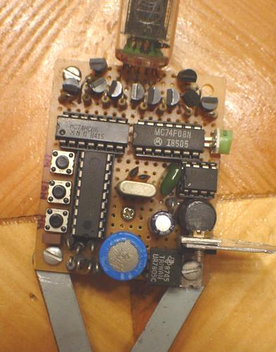
To avoid shopping, I dug through some of my old computer boards for the logic chips needed for this project. I found a 74HC86 quad XOR chip and a 74F08 quad AND chip. I only had to use two of the four AND gates in the 74F08 so I grounded the inputs of the unused AND gates. I programmed the PIC with my modified program, nixpropclk.asm. The HEX file which is used to program the PIC: nixpropclk.hex.
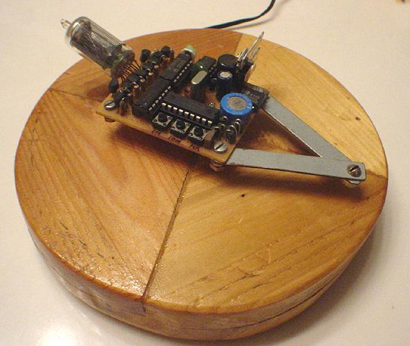
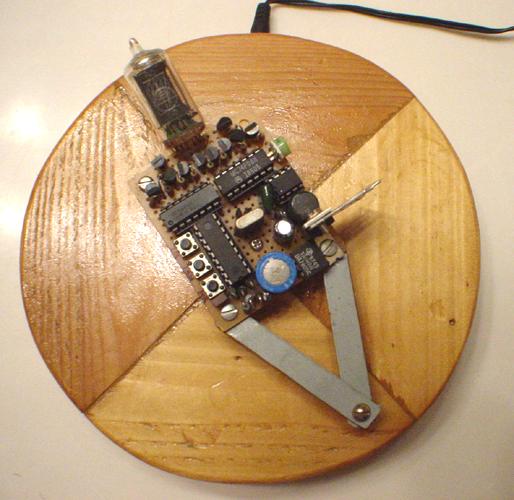
I stuffed the board with the PIC, the crystal oscillator, two logic chips, 10 HV transistors, the nixie, the HV inverter from a disposable camera flash circuit, the 7805 5V regulator, a 0.6 Farad memory cap, diodes, and the pushbuttons for setting the time. Rather than taking apart the motor to obtain power from the armature for the spinning board, I ripped apart another cheap motor and pulled out the armature and brush contacts and put it on the outside shaft of the other motor. The shaft was long enough for the armature and the cylinder that holds the spinning board. Many cassette tape motors are generally best for this purpose because of their long shafts which makes this possible. Moreover, this assembly allows for the armature to feed the spinning board constant power, i.e. 6 volts, and the motor can have a wide range of input voltages to adjust the speed. For best operation, my motor runs at 3 volts and the spinning board has about 6 to 7 volts. In the schematic below, the 0.6F memory capacitor and diode can be removed and the 5V can supply the VDD connections directly if one uses a separate armature on the outside of the motor to supply the constant power like I did. However, if one decides to modify the motor and obtain power directly from the armature of the motor itself, then the 0.6F capacitor and diode is needed to keep the PIC running to store the time changes while the board is not spinning. Below is the schematic diagram of the nixie propeller clock:
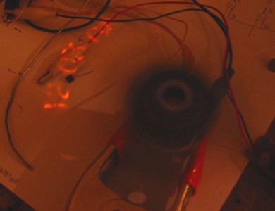
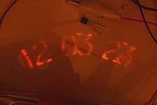
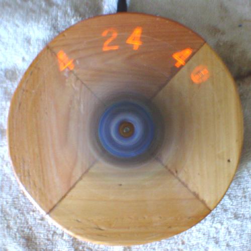
The only downfall of this nixie propeller clock is its relatively dim display that is not very visible in strong ambient light. The display brightness is slightly dimmer than nixie clocks with multiplexed displays and is best viewed in a relatively dimly lit room.
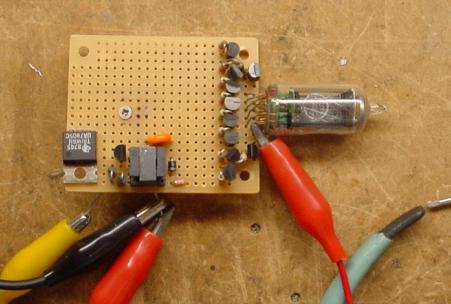
Construction and testing of HV generator
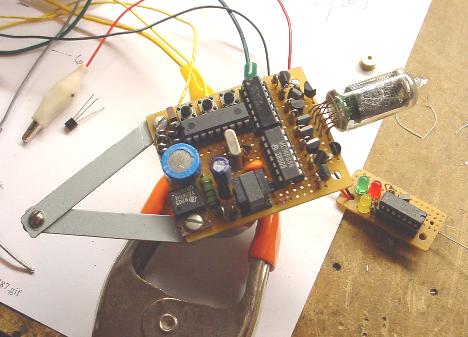
Clock without base
ADDITIONAL NOTES: Rather than using the logic gates to expand the 8-bit data output to 10-bits for each nixie cathode digit, one could use a 4028 BCD-to-decimal decoder. The character lookup table is simply changed to plain hex values so the port outputs BCD, as shown below:
The first 4 bits of port B are fed into the 4028 inputs, and the outputs are all fed to the cathode transistors of the nixie. The modification is shown below:
Please be cautious of the strange pinout of the 4028 and make sure the wiring is correct. Here is the assembly file with the modified character lookup table: nixpropclk2.asm and the HEX file: nixpropclk2.hex ready to program in the PIC. Please note that the software and circuit has not been tested, but theoretically they should work. If you build one and it works, please do let me know.
Additionally, a 7441 or 74141 BCD-to-decimal decoder would work and no high voltage transistors would be needed because they are built in these chips.
Back to Top