A Noisy High Voltage Generator
Return to Home
Return to Projects
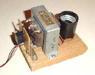
Since vibrators are no longer made today, I duplicated one using a small 5-volt relay from Radio Shack. The other materials used are an old transformer, light bulb socket, neon light bulbs, 9v battery jack, and a 9v battery. The transformer probably was used for audio output, but it is driven in reverse with the high-impediance primary as the high voltage output secondary.
The circuit produces high voltage as a result of inductive kickback from the transformer and can light up gas-filled bulbs or tubes. A 120V to 6V transformer will work, but the 6V secondary is driven by the relay. Your mileage may vary with other transformers. Moreover, the relay used in the circuit has an effect on the performance. Smaller relays such as PCB-mount types or reed relays are able to switch faster, thus driving the transformer at higher frequencies. Heavier duty relays are louder and oscillate slower, which often works best for larger iron-core transformers.
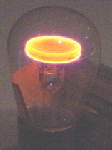
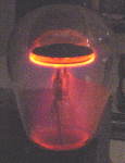
An interesting observation is that if a very small gap is added between the secondary of the transformer and the neon bulb, then the bulb acts like a miniature plasma globe because the spark gap increases the frequency. This tiny spark gap can be easily achieved by unscrewing the neon bulb slightly until the center connection barely makes any contact. The electrons attract to a grounded object like your fingers when touching the bulb. Shown below is the schematic diagram representation of the plasma globe circuit.
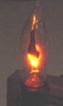
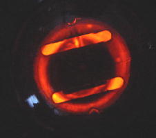
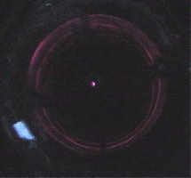
Below are pictures of the neon light bulbs acting like plasma globes.

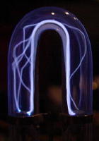
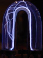
Another neat plasma display is to use a xenon-filled tube like those in flash cameras or strobe lights. Instead of using the neon bulb in the circuit, the transformer's secondary is connected to the two pins that feeds into the glass tube. The ring on the tube, which is used for triggering the discharge to create a flash, is left disconnected. Below are some pictures of the plasma effects in the xenon tube.

Many voltage regulator tubes are filled with a certain gas. At normal operation, some tubes can glow nicely such as the 0A3, (VR75), which is filled with some neon gas. A 0C3, (VR105) is filled with helium and some argon gas. The output of the transformer is hooked up to the plate and cathode pin. Below is a table of the pinouts for some gas-filled voltage regulator tubes.
| Tube Type | Plate Pin | Cathode Pin |
| 0A2, 0B2 | 1 or 5 | 2 or 7 |
| 0A3, 0C3, 0D3 | 5 | 2 |
| 874 | 3 | 1 |
Below are pictures of the top view of the 0A3 and 0C3 tubes respectively while operated by the circuit.
This simple circuit works quite nicely, although the relay can be loud. This project was built in 2003, and here is a video of it still working in 2024.
A further simplification of the original circuit can eliminate the transformer itself. The relay itself is a basic inductive coil with a switch attached to it. The original circuit described above operates because the relay oscillates by shorting out itself when the switch closes on the normally-open contact. Without the transformer, this would not be wise as the contacts would end up shorting out the power supply. Rather than using the normally-open contact, the simplified circuit makes use of the normally closed contact. Below is the schematic of the simplified relay high voltage generator:
Observe that the relay oscillates because as the coil begins to activate, the switch opens and disconnects the coil from the battery. During this moment the coil is disconnected, it will experience inductive kickback (high voltage) from the magnetic field collapsing around the relay coil itself. Furthermore, the switch will close when the coil has been disconnected, which will activate the coil once again. This results in oscillations.
I've observed that this circuit works best with relays that have an actual metal core inside the coil. In other words, reed relays won't work too well, if at all, because it is merely a coil with a switch inside. Medium and heavy duty relays work best. Lastly, the high voltage generated by the relay itself is not very powerful but it is sufficient to drive a small neon indicator bulb. I originally used this simple circuit as a non-solid-state approach for displaying the output bits rather than using LEDs in the Basic Relay Computer.