Digital AC Voltmeter
Return to Home
Return to Projects
I wanted a digital AC voltmeter to measure the output range from 0 to 150VAC with reasonable accuracy. Sure I could buy some premade DVM packages or use a microcontroller with a built-in ADC, but I wanted to make one from scratch myself using readily available parts I had on hand. I aimed for reasonable accuracy so I chose to have a 2 and a half display for the voltage, meaning the meter reads from 000 to 199. Below is the schematic of the AC DVM:
I used a voltage-controlled PWM circuit to convert an analog DC voltage to a pulse duty cycle. To do this, a 555 timer is used to generate a sawtooth wave at about 500Hz that is fed into a comparator to compare against the measured analog DC voltage. The output of the comparator has 500Hz period with a pulse width that is proportional to the input DC voltage. However, the sawtooth swing is only around 1.65 to 3.3V so a voltage divider between 5V and the measured DC voltage is used to offset and scale down the swing to this range. The 10K resistor on the sawtooth 555 timer is for adjusting the transistor bias to control the current going into the 0.1uF capacitor. Adjust this until the sawtooth is as clean as possible and has the 1.65-3.3V range and the correct frequency. Be careful not to adjust the pot all the way to ground or you could blow the 2N3906 transistor. Adding 1K resistors around the pot would be safer but I used just the pot to reduce parts count.
The circuitry in the upper half of the schematic could actually be used as a frequency counter. The CD4518 is a dual decade counter chip that is wired to count from 00 to 99. CPB~ to advance the B counter is negative-edge triggered so when the A counter transitions from 0111 to 1000, the fourth bit doesn't trigger the B counter. When the A counter rolls over from 1001 to 0000, the negative edge triggers B to advance once. The CD4013 flip-flop for the third digit advances on a positive edge clock, so a transistor inverter is used on the fourth bit from the B counter output so when it rolls over from 1001 to 0000, the transistor drives the CD4013 clock with a positive edge. The 74LS175 and second half of the CD4013 are used as flip-flop registers to grab the counter output for display on a rising edge of LOAD. Also, when LOAD goes high the CD4518 will reset to clear its counts.
To use the counter as a frequency counter, all one would need to do is feed 1Hz, 10Hz, etc. into LOAD to serve as the "gate." When measuring 60Hz for instance, the counter will count from 000 to 060 in 1 second and then the gate enables LOAD to reset the count and the 74LS175's grab 060 to display. The counter will again begin to count from 000 to 060 in the next second and so on. If the gate speed is raised to 10Hz then the counter only has 0.1 seconds to count and will count from 000 to 006, and multiply this by 10 to get the frequency representation. Essentially a 10Hz gate speed changes the frequency range from 000-199Hz to 0000 - 1990Hz. A 100Hz gate would have a range of 00000-19900Hz.
For the purpose of the DVM, the other 555 timer outputs very narrow pulses at around 100KHz. This ensures that up to 200 narrow pulses will fit in one 500Hz cycle and each pulse represents 1V. The output drives a transistor that is in parallel with the LM319 comparator output. Note that the LM319 has an open-collector output. Other comparators that do not have this feature will have to drive a transistor. The comparator output and the transistor with the 3.3K resistor create an AND gate. When the comparator output is not pulling down (i.e. logic 1), the CLK output will be driven by the 100KHz 555 to generate pulses for the frequency counter. When the duty cycle that is proportional to the measured voltage ends, the comparator output pulls down (logic 0) and CLK goes to 0. The frequency counter will count all the narrow pulses during this period, and the number of pulses represents the measured voltage provided the 4.7K and 10K pots are calibrated correctly. After a 500Hz cycle, the sawtooth starts again and LOAD goes high with a narrow pulse to signal to the frequency counter to grab the count to display as a voltage and reset the counter for the next measuring cycle.
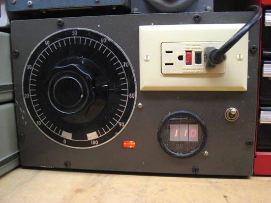
The AC measurement is done by converting 0-150VAC to a DC voltage determined by the 4.7K pot, which sets the DC range that is proportional to the AC input voltage.
Since the refresh rate is 500Hz, the display tends to jitter between values like 99 and 100 but placing a 4.7uF to 10uF capacitor on pin 5 of the LM319 comparator fixes the problem, but greatly reduces the response of the display to the actual voltage. If I set the variac to 120V and turn it on immediately, the display will start at 000 and gradually catch up to 120 in a couple seconds. A better fix is probably to reduce the 500Hz cycle to around 10Hz and reduce the 100KHz 555 timer frequency accordingly so about 200 pulses fit in one 10Hz cycle.
When correctly calibrated, the error from this voltmeter is around 5% at the worst, which is reasonably accurate enough for my purposes and gives me a good ballpark figure of what to expect out of the variac. I calibrated mine for more accuracy in the 100-140VAC range because that is where I typically set the variac.